The three sensors arrangement. Understanding the 3 wire sensor diagram: a comprehensive guide The standard measured by the three sensors: (a) diagram of the three
The three sensors arrangement. | Download Scientific Diagram
(a) three dimensions view of the proposed sensor. (b) diagrammatic
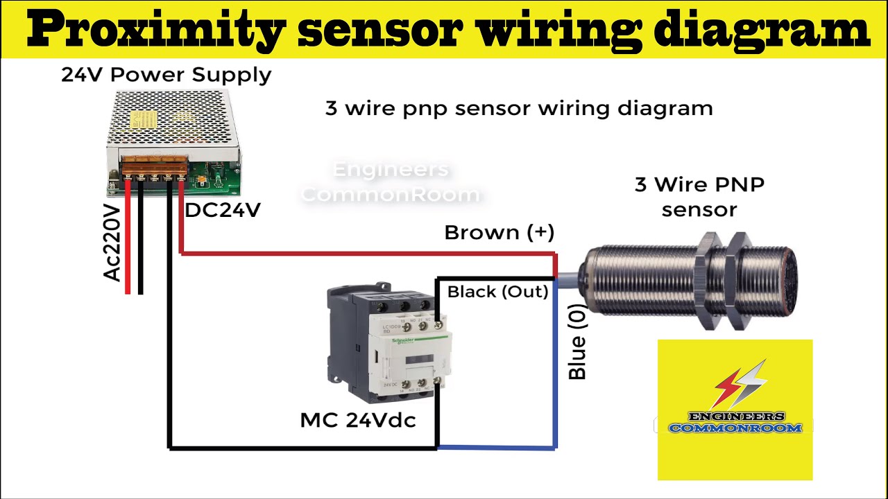
On video 3wire proximity sensor wiring diagram! how to use proximity
7.3 powerstroke sensor location diagramSensor and controller configuration for unit 7 Sept sensor schematics. detection elements are silicon detectors (d03 wire transmitter wiring diagram : 3 wire transmitter wiring diagram.
Schematic diagram and notations of the sensor system when measuring aInductive proximity circuit diagram Sensor resonant diagram block force innovative triple piezoelectric beam silicon thin films based3d diagram of the sensor..

Seven sensor box
1995 7.3l not starting, white smokeSchematic diagram of the sensors used within the model tests. figura 3 3: sensor overview [2]List of sensors?.
[diagram] 6 wire o2 sensor wiring diagram[diagram] 22re engine sensor diagram 1996 7.3 powerstroke map sensor location [limited unit]Fig. s3 schematic diagram of the sensor measurement..
[diagram] liftmaster sensor wiring diagram
Based on this diagram, what can you tell about these7.3 powerstroke sensor location diagram The three sensors arrangement.The three-dimensional schematic diagram of the sensor.
Innovative sensor designUnderstanding the 3 wire sensor diagram: a comprehensive guide 3 way occupancy sensor wiring diagram7.3 powerstroke sensor location diagram.
![[Explained] 7.3 Powerstroke Sensor Location Diagram+Video Guide!](https://i2.wp.com/www.automasterx.com/wp-content/uploads/2021/11/7.3-Powerstroke-Sensor-Location-Diagram-1024x605.jpg)
7.3 powerstroke sensor location diagram
7.3 powerstroke sensor location diagram[explained] 7.3 powerstroke sensor location diagram+video guide! .
.

![[DIAGRAM] 22re Engine Sensor Diagram - MYDIAGRAM.ONLINE](https://i2.wp.com/ls1tech.com/forums/attachments/conversions-hybrids/164079d1233618012-5-3-engine-picture-showing-sensors-334934.gif)


![3: Sensor overview [2] | Download Scientific Diagram](https://i2.wp.com/www.researchgate.net/publication/343789900/figure/fig4/AS:926945147637777@1598012353481/Sensor-overview-2.jpg)


